Wheeled Inverted Pendulum
Fall 2021 - Spring 2022Senior Design Project
Background
Because I want to work on controls systems in graduate school and as a career, I decided to focus my senior design project around the subject, concentrating on areas in controls I have not yet had the opportunity to work with. There were no options available that fit this criterion, so I collaborated with my mechatronics professor to design one.
Project Overview
A wheeled inverted pendulum (WIP) is a cart mounted with a pendulum that rotates freely at its base. The pendulum is balanced by a feedback control loop that commands the cart’s movement based on the pendulum’s position. WIPs serve as simplified models for balancing in higher dimensional systems, such as bipedal robots.

When balancing on an incline, a WIP must be able to measure the angles of the pendulum and the incline. Typically, this is done with gyroscopes, but they are prone to drift and loss of accuracy over time. University of Alabama PhD student Cole Woods proposed a sensor configuration and error algorithm that uses strictly accelerometer feedback to provide a full description of the state of the system and achieve balancing. This sensor configuration addresses the instability of the gyroscopes and produces a more robust controls system.
My team’s objective was to design and fabricate a WIP to validate balancing on variable inclines with the all-accelerometer sensing system and acceleration-based error algorithm. In my role as Controls Engineer, I focused on the implementation of the error algorithm, including angle estimation calculations, and writing the controls system software using a PID controller. I also served as the Team Lead and managed the other three team members.
Angle Estimation Calculations
The WIP had to be able to estimate the angles of the incline and the pendulum to find the error of the pendulum’s position using accelerometer readings and feedback from the motor mounted on the cart. The difficulty here laid in separating dynamic acceleration from gravitational acceleration, as they are combined in the readings from the accelerometers.
Pendulum Angle
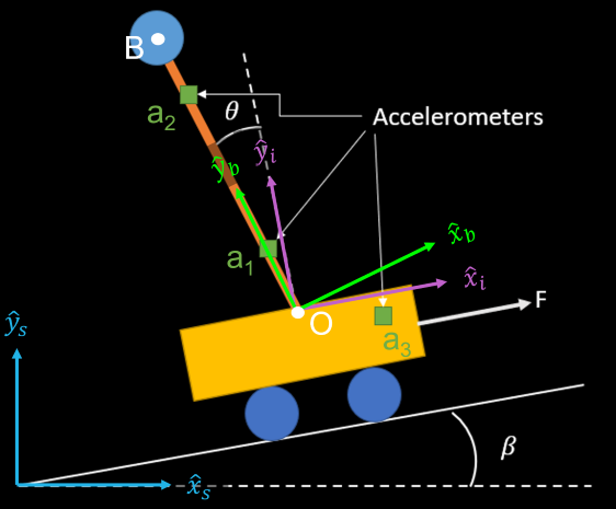
To calculate the pendulum angle, the readings from the two accelerometers on the pendulum were used to determine the acceleration of the base of the pendulum (point O in the diagram above). This acceleration is the same magnitude as the acceleration measured by the accelerometer mounted to the cart, but the former is in the pendulum’s coordinate system {b} and the latter is in the cart’s coordinate system {i}. The angular difference between the acceleration vectors is the rotation angle between the coordinate systems, which is the angle of the pendulum.
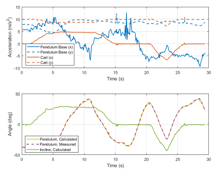
In the chart below, the upper plot shows the acceleration measured by the accelerometer mounted to the cart (orange lines) and the acceleration calculated at the pendulum base (blue lines). These are recordings from the actual system while the motor is not powered. The lower graph is the calculated angle (yellow line) based on the two acceleration readings. When the two acceleration readings are the same (when the solid lines intersect and the dotted lines intersect on the upper graph), the pendulum is normal to the cart, so it’s angle is zero. This is demonstrated the graphs.
A potentiometer mounted at the base of the pendulum also measured its angle (purple dotted line the lower graph) and served as validation for the angle calculation. The calculated and measured angles of the pendulum overlap, so the implemented angle calculation is accurate.
Incline Angle
For a cart that is not moving, the accelerometer on the cart only measures acceleration due to gravity. The angle of this vector is the angle of the incline. In order to measure the angle of the incline while the cart is moving, dynamic acceleration of the cart is estimated using motor feedback. This is subtracted from the x-direction of the accelerometer reading, and the angle of the gravity vector can be found using the resulting acceleration.
This can be seen in the chart to the right by comparing the readings from the accelerometer mounted to the cart (orange lines on the top plot) with the calculated incline angle (green line on the bottom plot). The cart was not moving during this demonstration, so the incline angle is simply the angle of the gravity vector.
